
PMESP® System
The Permanent Magnet Motor is an ideal driver for the centrifugal pumps used in the Electric Submersible Pump Industry. The MPS PM Motor can directly replace the Induction Motor that is used in the conventional ESP completions and provide significant operational benefits to the system.
The MPS PM motor can be operated from 50 RPM to 6000 RPM and therefore can be used very efficiently to optimize the production from the well and operate the pump at its Best Efficiency Point (BEP) at all times.
Applications of Interest
- ≻ Gassy wells
- ≻ Wells with low producing fluid levels
- ≻ Wells in which an ESP system may be installed below the perforations
- ≻ Wells with long perforation Intervals
- ≻ Wells with scale issues due to motor heat rise
- ≻ High dog leg severity applications
- ≻ Fields with limited electrical power availability
Associated Benefits
- ≻ High electrical and mechanical reliability
- ≻ Electrical power cost savings
- ≻ Short length allows deployment in crooked wells
- ≻ Low heat rise will extend motor runlife
- ≻ Minimum electrical losses at low loads
- ≻ High Starting torque to free stuck pumps
- ≻ Low repair cost
- ≻ Short installation time
Salient Features
- ≻ High Efficiency
- ≻ High Torque across wide HZ/RPM operating range
- ≻ High HP per unit length
- ≻ Small oil expansion volume
- ≻ No rotor magnetization current and very low inrush/starting current
- ≻ Very low idle current
- ≻ Current linear with load even at low loading
The low heat rise in the PM motor reduces the operating temperature of the internal components of the motor including the motor winding (magnet wire). This increases the reliability of the motor significantly and in some unconventional installations of the ESP system in applications where there may be low or no flow of fluid past the motor, like installation of the MPS PMESP® system below the perforations without a shroud or a recirculation tube, prevents the motor from overheating and causing a failure.
The significantly shorter length of the motor increases the overall reliability of the motor as there are fewer rotors and rotor bearings (rotating parts)
Motor Efficiency and Power Cost
Due to its unique control methodology, MPS PMMs are designed to operate at maximum efficiency and they will operate at a minimum average 10 percentage points higher efficiency than an equivalent Induction Motor (IM).
Running a MPS PMM instead of an IM will result in power saving of more than 20%. The saving would be higher for gassy wells and with systems where the motor is designed to be lightly loaded.
Reliability
MPS Permanent Magnet Motors (PMM) are efficient electrically, have low internal mechanical friction, low internal heat rise and are significantly shorter than equivalent Induction Motors. These fundamental characteristics of PMM clearly address most of the failure modes related to Induction Motors in ESP applications.
The MPS PMESP system is designed with complete focus on system reliability.
Repair Cost
MPS PMM stators will be on average 50% shorter than the equivalent Induction motor stators and there are fewer rotors in the motor which enable quick repair and reduced assembly time. The high salvage rate of the PM rotors also help in significantly reducing the repair costs of motors.


Gassy wells
One of the main challenges when operating ESPs in wells with high Gas Volume Fractions (GVF) is slugging. Many devices have been developed to improve pump performance in high GVF environments, but when the well is slugging, induction motors driving an ESP will over heat and will most likely shut down on high motor temperature as the motor losses at low load are high even when the gas surrounding the motor has no heat transfer capacity to cool the motor.
PM motors react differently to gas slugs: Motor current will be reduced proportionally to the load and hence motor heat rise will be minimised. Furthermore, the motor current measured at surface is directly proportional to the pump load and will provide a quick and quantitative indication of well behavior.
Product Portfolio
| Series* | OD | Max HP (3600 rpm) (Single Section) |
Max. Well Temperature | Max. Winding Temperature | Max. Length | Max. Efficiency |
| 375 | 3.75” | 250 | 350 F | 400 F | 30 Ft. | 92 % |
| 456 | 4.56” | 450 | 30 Ft. | 94 % | ||
| 562 | 5.62” | 1000 | 30 Ft. | 95 % | ||
| 738 | 7.38” | 2250 | 32 Ft. | 96.5 % |
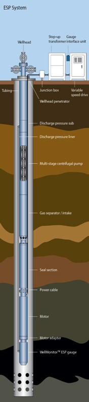
ESP SYSTEM COMPONENTS
Motor Seals
Magnetic Pumping Solutions offer a complete range of Modular Motor Seals that have been designed for installation with all motor series. The Motor Seal plays a very important part in the proper functioning of the Permanent Magnet Motor driven Electric Submersible Pumping System and is a key component that affects the run-life and performance of the system. The Motor Seal is located above the top motor in a standard ESP installation and connects the motor to the Intake module or the Gas Separator.
The main functions of the Motor Seal are;
- To act as a barrier between the well fluid and the clean motor oil.
- To equalize the pressure in the motor with the annulus pressure.
- To transfer the torque developed by the motor to the Intake / Gas Handler section.
- To act as a chamber that allows the expansion and contraction of motor oil during the operation of the ESP System.
- To carry the Thrust Bearing that absorbs the down thrust forces developed by the pump during operation, which is critical when using pumps built in compression construction.
Intakes, Gas Separators & Gas Handlers
Magnetic Pumping Solutions offer a wide range of Intakes, Gas Separation and Gas Handling devices that enable the successful application of the Electrical Submersible Pump technology in wells with high GOR, that require artificial lift. The products offered by MPS include
- Intakes - Standard and Integral.
- Gas Separators - Rotary and Vortex types.
- Gas Handlers - Low and High Flow types including Axial Flow Pumps
Pumps
Magnetic Pumping Solutions offer a complete range of Electrical Submersible Pumps for Oil and Water applications. These pumps are multistage in design and each stage consists of an impeller that is mounted on the shaft and rotates with the shaft during operation and a diffuser that is stationary and mounted in the housing of the pump. The pumps are selected based on the construction of the well and the desired flow rate from the well. The stage type selected determines the flow rate and the number of stages selected determines the head or lift produced by the pump.
All pumps are tested as per API recommendation 11S2. The test results must fall within +/-5% on Head produced, +/-8% on Horse Power across the Recommended Operating Range and a maximum deviation of –10% on efficiency at Best Efficiency Point.
- 338 Series
- 250, 550, 1200, 2000, 2500.
- 400 Series
- 180, 350, 450, 700, 850, 900, 1050, 1200, 1750, 2200, 3000, 4300, 5800.
- 513 Series
- 1600, 2500, 4000, 6000, 7500, 10000.
- 538 Series
- 1500, 2500, 3500, 4250, 5500, 7000, 11000.
- 675 Series
- 7000, 10000, 16000, 21000.
- 862 Series
- 19000, 26000.
- 950 Series
- 34500.
The sizes listed in bold are mixed flow stages.
Power Cable
Magnetic Pumping Solutions offer the MAG-LINE range of Cables that are suitable for installation with ESP systems in oil, water and gas producing wells. The ESP cable is a special product that is specially engineered to work under the extreme conditions in an oil well. Oil wells are very diverse in nature, with regard to setting depth, temperature, pressure, presence of corrosive/erosive and well dimensions. These variations call for careful selection of the cable design for each different application. Cable in Flat or Round profile, with Galvanized, Stainless Steel or Monel Armor, Solid or Stranded Conductor and ones with or without capillary tubes are available.
Surface Accessories
Magnetic Pumping Solutions offer a complete range of Surface Accessories required for the installation and operation of the ESP system. This includes the Step-Up / Step-Down Transformers, Junction Boxes, Surface Skids, Surface Cable and Penetrator Systems. The PM Junction Boxes are specially designed and manufactured to address the safety requirements necessary for downhole PM Motor driven lift systems. The Transformers can be Dry Type or Oil Filled (ONAN) type as required by the client and based on the power ratings. The MPS PM Step Up Transformers are typically 2/3 the size of standard induction motor Step Up Transformers. The Surface Skids can be Open, Protected or Enclosed type based on client requirements and with Air-conditioning as an option for hot weather / desert applications.
